Copyright 2022 IEW Solutions an ifelseWare Conpany
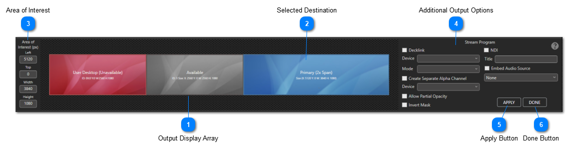
Display Selection Panel
This panel appears over the clip thumbnails after you click ‘Select Video Display Output’ under the Settings menu.
Output Display Array
The array is much like the one found in Windows “Display Settings” It illustrates the current layout (resolution size and position) of all attached monitor outputs. Legion constantly monitors for any changes to this layout and will update accordingly.
NOTE: To ensure proper setup, the output that has been designated the systems primary user desktop will appear as red and cannot be selected for use. Do not confuse this with Legion’s ‘Primary’ designation, that is simply the apps way illustrating the one that is selected for program out.
To select the program output, simply right click on the desired display and select "Make Primary". When the primary is selected the tile will become blue.
Cloned:
If needed, you can select another output to be a clone of the primary one. This can be handy in situations where a separate alpha mask is needed for a downstream key.
To select, right click on any gray tiles and select “Clone Primary”.
If the cloned output is to be used as an alpha key, that output will need to desaturate all color and/or invert its light and dark shades. Selecting either or both will affect the change.
Spanned:
Another feature is the ability to create spanned pixel spaces. A spanned space effectively extends a single program output across multiple display screens. This is useful when needing to display ultrawide resolutions that exceed the capability of a single output.
To prepare for a spanned space, first go to Windows Display Settings and ensure that all outputs you wish to use are aligned in the pattern that you require. For example, if you need to provide enough outputs to cover a resolution of 7680 x 1080 then you would need to arrange them all horizontally from left to match the physical arrangement of projectors keeping in mind the display index does not necessarily reflect their physical arrangement.
Another example would be like a video wall. You want to display 3840x2160 media using four 1920x1080 monitors.
Now once that has been done you can come back to Legion’s display selection panel and setup the span by first selecting the top and left most output in your arrangement.to be the primary.
Next right click on the right and bottom most output and select “Span With Primary”.
Area of interest outlines the position (Left & Top) and size (Width x Height) of the Primary/PGM rendering canvas. The positioning values are relative to the systems overall extended display space. It is important to remember that in Windows, 0 X or Left and 0 Y or Top are found at the top lefthand corner of the display that has been assigned as the user’s primary desktop. In Legion this is displayed as the red tile.
Any positioning to the right or below the primary desktop display are positive numbers and ones to the left or above the primary desktop is reflected as negative a number.
After you first select which displays will be Legion’s primary outputs (Including Spans), you are free to manually adjust these numbers. This is handy when outputting to an LED wall that has a nonstandard resolution or one that is smaller than the EDID being provided to the legion computer.
For example, we are providing media for an LED wall resolution of 3528 x 980 (3.6 aspect ratio) but are connected downstream to a device that can’t provide a custom EDID for that resolution. In this case you would either span two standard 1080p outputs which totals to 3840x1080. This is OK but it may be tricky to work the asset geometry because Legion would produce a rendering canvas of that entire oversized space meaning the geometry fit and position snaps would be incorrect. The better way is to adjust the area of interest to match the wall’s resolution. This also resizes the preview and program monitoring aspect to match as well as all snaps will now use the AOI as its parameters.
NOTE: If when adjusting the space goes out of bounds of the primary display space a red crosshatch pattern is seen in the overflow area.
You have to ability to also output all program activity directly to either a Decklink SDI output and/or NDI stream. This can be done whether or not you are already outputting to a conventional HDMI and/or DP type monitor.
Decklink:
Check to enable the use of a Deckink card as an output.
Device:
Select the appropriate Decklink output.
Mode:
Select the desired SDI resolution.
Create Separate Alpha Channel:
As it implies, check if you need to use another available Decklink SDI output for use as an additional alpha key mask that clones the primary SDI output.
Allow Partial Opacity and Invert Mask:
Each are used to adjust the key’s visual characteristics.
NDI:
Check to create an NDI stream of the program output.
Title:
This is the label that is visible on the receiving end designating the feed.
Embed Audio Source:
Check this to also send program audio with the video feed. Be sure to select the correct audio output device whose signal you want streamed.